Dr. Vadym Zayets
v.zayets(at)gmail.com
My Research and Inventions
click here to see all content |

Dr. Vadym Zayetsv.zayets(at)gmail.com |
|
|
IntroductionExperimental observation of transverse MO effectProperties of transverse MO effectOrigin of transverse MO effectTransverse EllipticityTwo contributions to transverse MO effectMagnetization-dependent optical lossCalculations of transverse MO effect in the case of multilayer structureOptical excitation of spin-polarized electrons utilizing transverse MOPlasmonsGiant Enhancement of Transverse MO effectHistory and Future |
Transverse Magneto-Optical effect
Transverse EllipticityThe transverse ellipticity is crucial for light to experience transverse MO effect. Only light, which transverse ellipticity is close to circular, may experience significant transverse MO effect.How to describe mathematically elliptical polarization of light
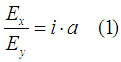
The following describes conventional polarization of light, which light may have when it propagates through a bulk material. Figure 1 shows conventional longitudinal ellipticity of light. The polarization is rotating in xy-plane, which is perpendicular to light propagation direction. The y-component of the polarization legs behind x-polarization. Therefore, the polarization can be describe as
In cases of a=1 and a=-1, the polarization is left and right circular, respectively. In cases of a=0 and a=infinity, the polarization is linear. In all other cases, the polarization is elliptical.
When light may have transverse-elliptical polarization
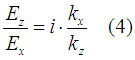
Only light, which polarization is transverse elliptical, may experience the transverse MO effect. Since an electromagnetic wave is transverse and transverse elliptical polarization clearly has a component along propagation direction, it seems that such a polarization is forbidden. However, there is one special case when such a polarization is possible. It is the case when light has an evanescent component along the direction perpendicular to the wave propagation direction. Light may have the evanescent component when it propagates in vicinity of an interface between two different materials. For example, if the wave propagates along z-direction, but it has evanescent component along x-direction. In this case the x-component of the wave vector has only an imaginary part and the z-component has only a real part. So the wave is described as |
|
||
Fig.3 Rotation of polarization of wave is similar to rotation of wheels of train in case of transverse ellipticity and to rotation of airplane propeller in case of conventional longitudinal ellipticity |
It is interesting to known how large the transverse ellipticity in known cases when the transverse MO is experimentally observed.
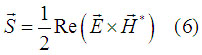
The transverse ellipticity is calculated as
Figure 4 shows calculated transverse ellipticity in cases of a waveguide mode propagating in Fe/AlGaAs, Co/AlGaAs, Ni/AlGaAs waveguides (buffer Al0.5Ga0.5As(300 nm)/core Al0.3Ga0.7As(1200 nm)/ clad Al0.5Ga0.5As) and in cases of a surface plasmon propagating along Fe/air, Co/air, Ni/air interfaces. In all cases the traverse ellipticity is significant. The ellipticity is close to circular for the waveguiding mode. That is the reason why the experimentally observed transverse MO effect in waveguides is substantial.
In both cases of the hybrid waveguide modes and the surface plasmons, the transverse ellipticity is substantial.
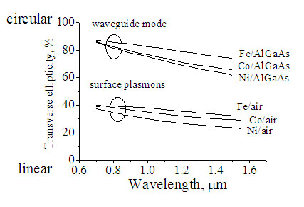 |
Fig.4 Transverse ellipticity of waveguide mode propagating in metal/AlGaAs waveguide and surface plasmon propagating at metal/air interface. 100% corresponds to a circular polarization. The upper and lower insets show the optical field distribution of a waveguide mode and a surface plasmon, respectively. |
I will try to answer your questions as soon as possible